owa5X Data Logger
The current VDS data logger is the Owasys owa5X. It records CAN, XCP/CCP, UDS and OBD traffic, carries a GPS receiver and a cellular modem, and is powered from the vehicle at 9 to 36 V DC.
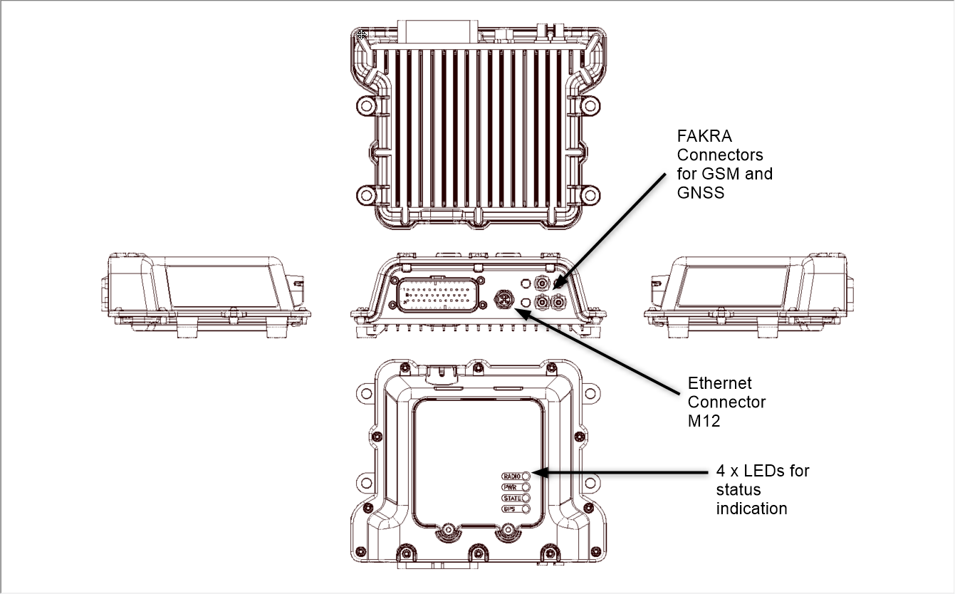
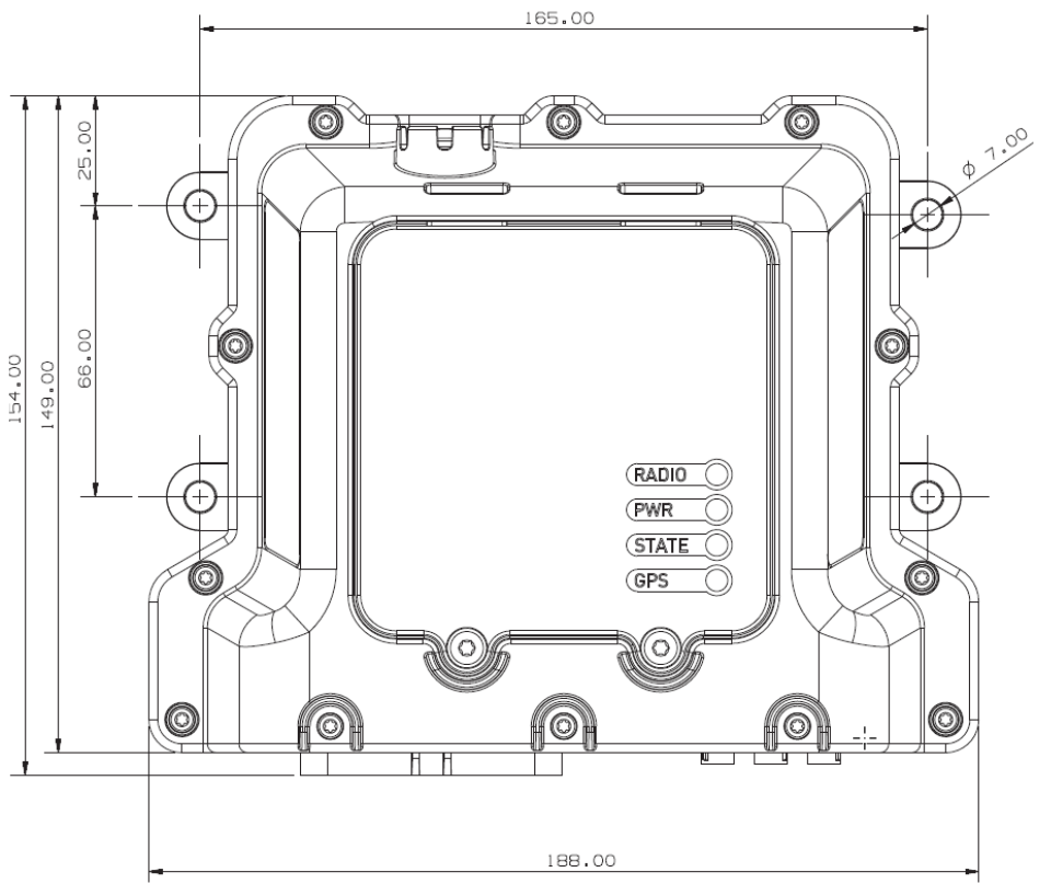
Status LEDs
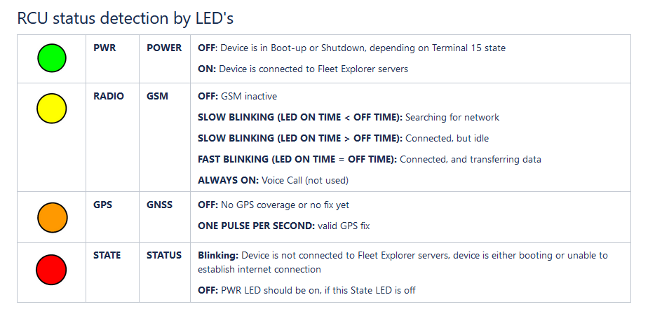
The two software-controlled LEDs on the top of the owa5X show the connection state of the logger:
| LED | Meaning |
|---|---|
| Green blinking | Connecting to the VDS backend |
| Green solid | Connected to the VDS backend and exchanging data |
| Red blinking | Temporary error, the logger keeps retrying (for example no cellular connection yet) |
| Red solid | Permanent error, the logger needs attention |
After power-up there is a short delay before the LEDs light. If the red LED stays on, see Device Troubleshooting.
Power Consumption
Typical consumption of the owa5X at 24 V DC:
| State | Current |
|---|---|
| Off | 0.98 mA |
| Standby | 12.64 mA |
| Run | 51.95 mA |
| Run with cellular and GPS active | 92.60 mA |
Harness
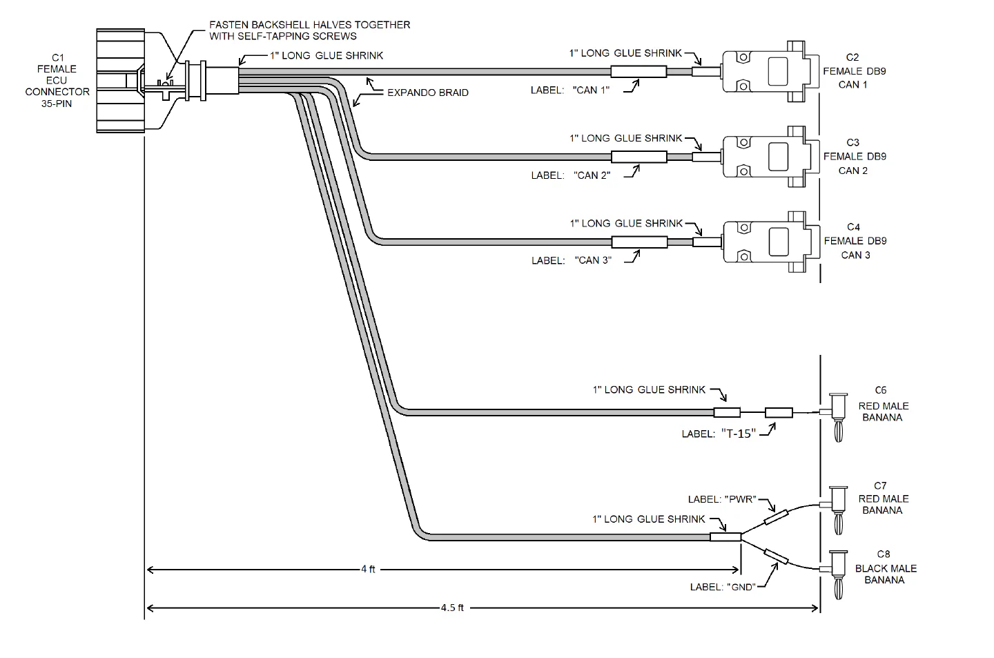
The harness consists of:
- One 35-pin female ECU connector (to the logger).
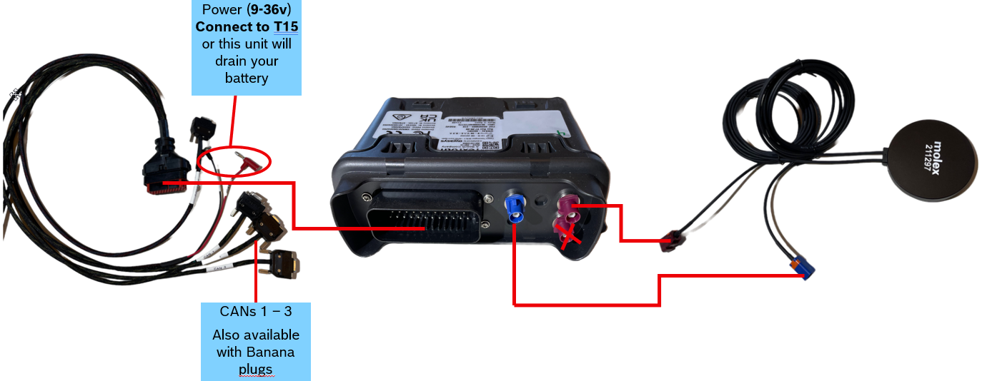
- Three female DB9 cables for CAN 1 to CAN 3. Yellow is CAN High, green is CAN Low. The DB9 connectors can be removed in favour of banana plugs for use with a breakout box.
- Two male banana cables for power, 9 to 36 V DC, about 3 ft long.
- One male banana cable for T-15 (ignition).
Earlier Hardware: owa4X
Some fleets still run the earlier owa4X logger. It is configured and used the same way as the owa5X; the differences are physical.
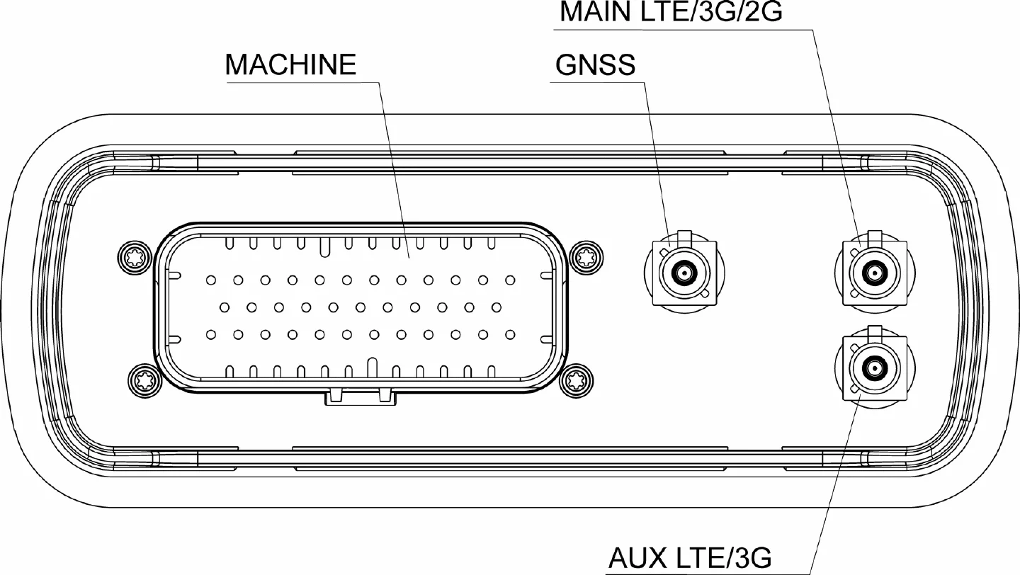
Connections. The antenna sockets differ from the owa5X: with an antenna that has two purple Fakra connectors, CELL1 connects to the top socket and CELL2 to the bottom.
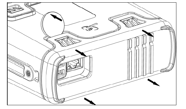
SIM and SD card. The cover is held by four snaps and can be prised off with a coin. The SIM and SD card sit under it.
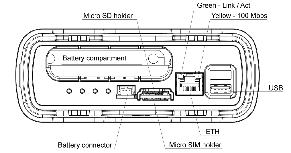
Front and rear IO.
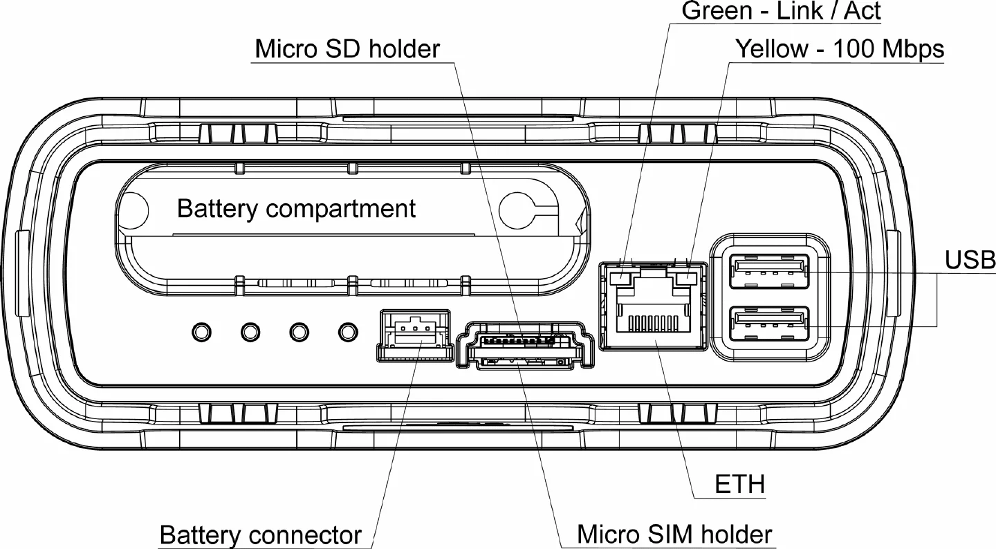
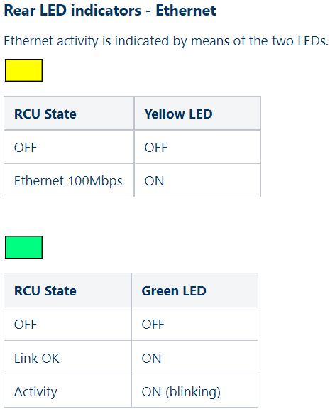
Ethernet activity lights.
The owa4X exposes its CAN interfaces as can1 to can3 where the owa5X uses canfd1 to canfd4; this matters when mapping buses to interfaces on the Assignments page.