What Vehicle Data Solutions Is
Bosch Vehicle Data Solutions (VDS) collects telemetry from the vehicles of your development fleet and makes it available in the cloud: as live signals in Grafana, as downloadable measurement files, and through a REST API. The service consists of:
- Software as a service: the cloud backend, the web application and the integrated services, operated by Bosch.
- Hardware bundle: a telematics data logger based on automotive standards, with its antenna and harness.
- Operations and support: the product is fully operated by Bosch. Support is reached at vds.support@us.bosch.com.
This page takes you from an unopened box to the first recorded trip. The exact hardware bundle you receive may differ slightly from the pictures.
Hardware Bundle Contents
- owa5X data logger
- Antenna (4G/GPS)
- Harness (CAN/Power)
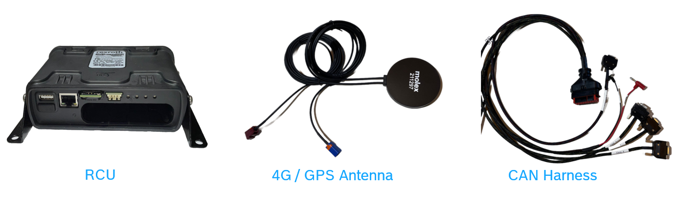
Connectors, LED meanings, dimensions and power consumption are on the Hardware page. That page also covers the earlier owa4X logger, which a few fleets still use.
Install the Device
Your device arrives fully configured and registered to your VDS project. Installation is a matter of connecting it.
- Connect the antenna and the harness to the logger. With an antenna that has one cellular (purple Fakra) connector, use the bottom purple socket. With two cellular connectors, CELL1 goes to the bottom socket and CELL2 to the top.
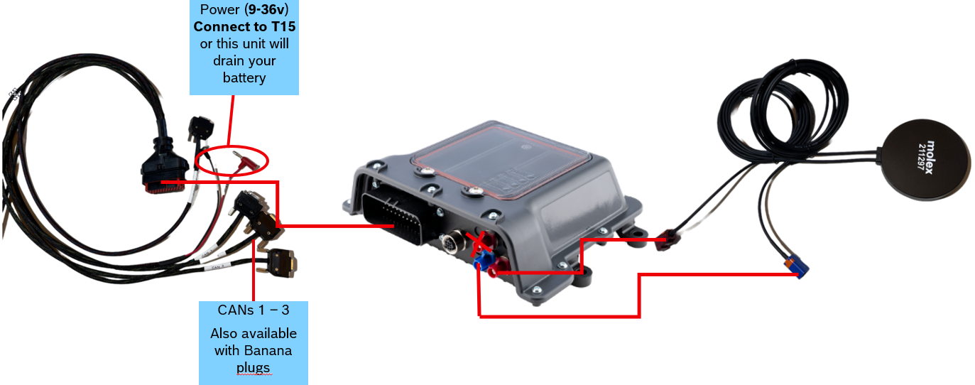
- The harness has a separate plug for T-15 (ignition). Wake and sleep on T-15 is disabled by default, so you may leave it disconnected, connect it to T-15 of the vehicle, or connect it to KL-30. If you want the logger to wake and sleep with the ignition, contact support.
- Connect the CAN interfaces of the harness to the vehicle buses you want to record. Note which physical interface (CAN1, CAN2, CAN3) goes to which bus: you will map them to named buses in the web application in the next step.
- Power the logger with 9 to 36 V DC. After a short delay the LEDs start: green blinking while the logger connects, green solid once it is connected to the VDS backend. A red LED means an error; see the Hardware page for the full table.
Set Up Your Project
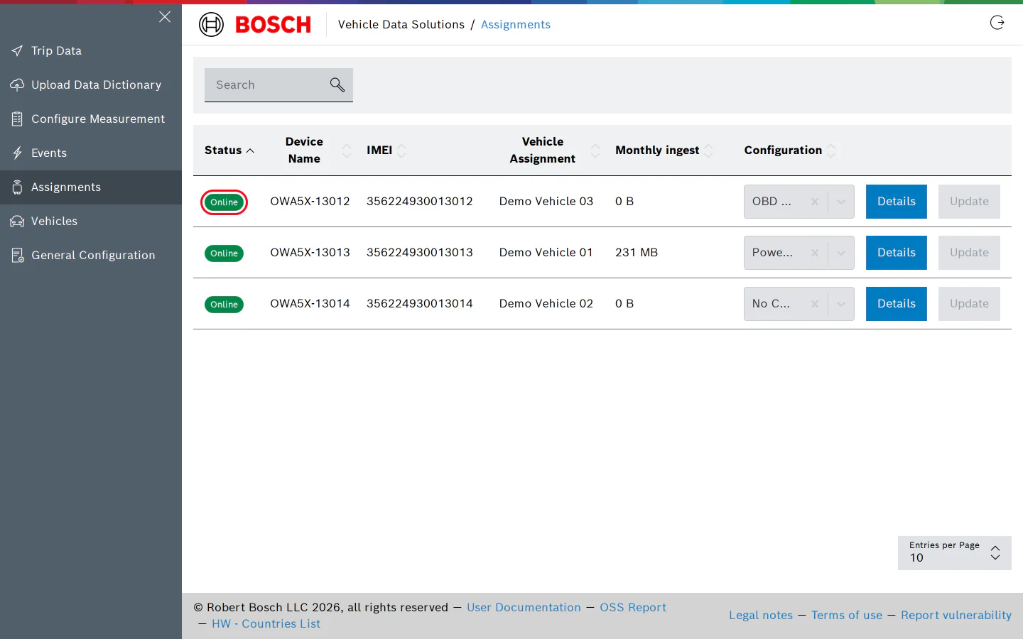
Once the green LED is solid, the device appears with an Online badge on the Assignments page of the web application.
The remaining setup happens in the web application, in this order:
- General Configuration: name the vehicle buses your fleet uses, for example “Powertrain CAN”.
- Vehicles: create a vehicle for each car and give it attributes such as its VIN and time zone.
- Upload Data Dictionary: upload the DBC, ARXML, A2L or XLSX files that describe the signals on those buses.
- Configure Measurement: choose which signals to record, at which rate, and whether to record MF4 files on the device.
- Assignments: assign the device to its vehicle, map each bus to the physical interface it is wired to, and assign the configuration. The device starts recording as soon as the configuration reaches it.
Recorded trips then show up on Trip Data, and the signals in Grafana.
If the Device Does Not Come Online
Most first-day problems are the physical connection or the cellular link. Check the antenna and harness are seated, the SIM and SD card are installed, and the supply is within 9 to 36 V. The Device Troubleshooting page walks through the remaining causes symptom by symptom, and the Device Web Manager page explains how to inspect the logger over its Ethernet port.